You are using an out of date browser. It may not display this or other websites correctly.
You should upgrade or use an alternative browser.
You should upgrade or use an alternative browser.
Mauser K98 blueprints
- Thread starter bruce98k
- Start date
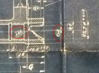
I believe Karabiner 98k vol 2 has the drawing at a much higher resolution. I was struggling with those as well. I believe the dimension giving a width is 4.1 and not 4.7, and the one specifying the distance from the centerline I couldn't confirm.The image attached has highlighted unclear dimensions, where I need some help. Any idea?
I've been very busy with school work, haven't gotten to do any work on the project directly, mostly just surrounding research. Will almost have a prototype of the bolt made to the tolerance specified in the drawings within a half year, which I will then go and test in a bunch of original production rifles to confirm the tolerances.
gewehr98guy
Registered
Hi, do you by chance, have any blueprints for the gewehr 98's lange visier rear sight. Im trying to machine one for a project, blueprints would be a big help, thanks in advanceView attachment 404805View attachment 404806
Hello everyone, can anyone tell me that these two pictures originated from that book (forgive me for bad English)
I will sort through them after I finish work today, but I have had a great victory on the document front. I requested digitization of a group of file sets from the German archive office in Freiburg, did a quick run through and document set 'RH 8/3307A' has drawings covering the bolt, receiver, and the stock for the k98k in very high resolution.
Document set RH 8/5872 also got digitized and contains the acceptance gauges(?) used by the WaA for k98k rifles. It is signficantly chunkier and will take longer for me to go through.
Document set RH 8/5872 also got digitized and contains the acceptance gauges(?) used by the WaA for k98k rifles. It is signficantly chunkier and will take longer for me to go through.
The digitized copies are free to access and request. The wait time for digitization is 4-6 weeks. You can access the files I got digitized right now through invenio and the specific document group is in a zip file you can download from this google drive link hereWould love to get copies, or pointed to the right office to purchase digitized copies myself. Thanks!
Edit: I am also waiting for the digitization of the file group that should include the engineering drawings for the k43(RH 8/3308k), I'll post when those get put up as well.
Fal Grunt
Senior Member
I would absolutely love the drawings for the k43.
I'm curious what search terms you used to find the RH 8/3307A drawings? I've spent MANY hours looking through that archive and I am embarrassed to say I never found them!
Absolutely amazing, I've spent hours searching that archive, and now apparently there is a ton of stuff. I spent several hundred dollars (close to $1k) getting drawings from another German archive that now are FREE!
Last edited:
I went through the document lists for both the WaA and the... I forget the German word but the Prussian Rifle Proofing Comission and tried to find anything labeled technical documents. There are also a bunch of WaA documents covering artillery, flamethrowers, tanks, landmines, grenades, and other info in the RH 8 file group. The most numerous thing was actually technical documents regarding different fuses for grenades and various artillery types.I would absolutely love the drawings for the k43.
I'm curious what search terms you used to find the RH 8/3307A drawings? I've spent MANY hours looking through that archive and I am embarrassed to say I never found them!
Also can you send a link for the RH 8/5872?
RH 8/5872 is significantly larger than 3307A. I am uploading it to drive right now but might not be able to get it up before I leave for work, you can also download it through invenio(and that might be faster than downloading the .zip file through drive).
Fal Grunt
Senior Member
I found it, and am downloading it.I went through the document lists for both the WaA and the... I forget the German word but the Prussian Rifle Proofing Comission and tried to find anything labeled technical documents. There are also a bunch of WaA documents covering artillery, flamethrowers, tanks, landmines, grenades, and other info in the RH 8 file group.
RH 8/5872 is significantly larger than 3307A. I am uploading it to drive right now but might not be able to get it up before I leave for work, you can also download it through invenio(and that might be faster than downloading the .zip file through drive).
I'll go through the RH 8 files a little closer and see if I can find anything else.
Thanks a ton!
No problem.I found it, and am downloading it.
I'll go through the RH 8 files a little closer and see if I can find anything else.
Thanks a ton!
To request digitization you just send an email to the office which contains the documents. All military records are contained in the Freiburg im Breisgau office, and the email to contact is benutzersaal.freiburg@bundesarchiv.de
Alright, now that I can sit down and read the documents, I have begun translating these surface callouts and wanted to make sure I am correct.I found it, and am downloading it.
I'll go through the RH 8 files a little closer and see if I can find anything else.
Thanks a ton!

In this table, if I am translating it right, it means
-glatte Fläche - as forged/minimally processed. In original manufacture this meant basically descaleing and nothing else.
-Schuppfläche - Rough machined, tooling marks remain but not finish machined.
-Schlichtfläche - Finished machined. Ie with a climb cut performed to reach final dimensions.
-Feinschlichtfläche - Very fine surface, so one that has been polished or ground as the final shaping operation.
If I have these correct, then I can use the notes I have taken to reference the surface finish tables I have in a few textbooks to give actual callouts on the drawings I produce. Also, the oval symbol just calls out dimensions which were given special attention by the WaA before accepting the part.
Fal Grunt
Senior Member
Alright, now that I can sit down and read the documents, I have begun translating these surface callouts and wanted to make sure I am correct.View attachment 432091
In this table, if I am translating it right, it means
-glatte Fläche - as forged/minimally processed. In original manufacture this meant basically descaleing and nothing else.
-Schuppfläche - Rough machined, tooling marks remain but not finish machined.
-Schlichtfläche - Finished machined. Ie with a climb cut performed to reach final dimensions.
-Feinschlichtfläche - Very fine surface, so one that has been polished or ground as the final shaping operation.
If I have these correct, then I can use the notes I have taken to reference the surface finish tables I have in a few textbooks to give actual callouts on the drawings I produce. Also, the oval symbol just calls out dimensions which were given special attention by the WaA before accepting the part.
Surface Roughness Conversion Chart Tables
Surface Roughness Conversion Charts and Tables, definitions and data. Where: Ra = Roughness, average in micro-meters & micro-inches, RMS = Root Mean Square in micro-inches, CLA = Center Line average in micro-inches
www.engineersedge.com
This will help you with the conversion.
Yes, basically your descriptions are correct from a modern perspective.
I downloaded and took a look at RH 8/5872, I have the earlier version of this document (cost me a fortune!) with the written instructions on inspection. However, most of the gauges are the same or very similar. I will have to print it out and compare it.
Another situation where my lack of GD&T knowledge has bitten me, the method used in the documents is listed in your link.Surface Roughness Conversion Chart Tables
Surface Roughness Conversion Charts and Tables, definitions and data. Where: Ra = Roughness, average in micro-meters & micro-inches, RMS = Root Mean Square in micro-inches, CLA = Center Line average in micro-incheswww.engineersedge.com
This will help you with the conversion.
Yes, basically your descriptions are correct from a modern perspective.
I downloaded and took a look at RH 8/5872, I have the earlier version of this document (cost me a fortune!) with the written instructions on inspection. However, most of the gauges are the same or very similar. I will have to print it out and compare it.
A question for you. I have access to a lathe(with a four jaw chuck and the usual kit), verticle mill, and a hydraulic press. I recognized at the start of this project that the internal camming surfaces would need something weird to actually impliment, and with more knowledge I have come to the conclusion that I would need either a machine capable of live tooling or a shaper(though I am not sure how this would work, only that people recommended this method on a machinist's forum). My plan for this is to do some engineering to make a mini-shaper that grinds out the cam incrementally; however, on revisiting the documents I've realized that I overlooked the raceways in the receiver.
How would I do these without eliminating the bolt overtravel stops at the end of the receiver? The guide which started this project (linked here) uses ground down standard sized broaches to get them to near finished, then a file to get the final profile, however this method eliminates the overtravel stops as previously stated. The only tool that I can see being able to do this is a shaper, that is unless I include the idea into the 'mini-shaper' concept said previously.
I don't know. What is your take on it? Am I missing something that is obvious?
Either way, I need to revisit my kinematics
Guillaume d'Orange
Senior Member
Is your project about building a K98k at home ?Another situation where my lack of GD&T knowledge has bitten me, the method used in the documents is listed in your link.
A question for you. I have access to a lathe(with a four jaw chuck and the usual kit), verticle mill, and a hydraulic press. I recognized at the start of this project that the internal camming surfaces would need something weird to actually impliment, and with more knowledge I have come to the conclusion that I would need either a machine capable of live tooling or a shaper(though I am not sure how this would work, only that people recommended this method on a machinist's forum). My plan for this is to do some engineering to make a mini-shaper that grinds out the cam incrementally; however, on revisiting the documents I've realized that I overlooked the raceways in the receiver.
How would I do these without eliminating the bolt overtravel stops at the end of the receiver? The guide which started this project (linked here) uses ground down standard sized broaches to get them to near finished, then a file to get the final profile, however this method eliminates the overtravel stops as previously stated. The only tool that I can see being able to do this is a shaper, that is unless I include the idea into the 'mini-shaper' concept said previously.
I don't know. What is your take on it? Am I missing something that is obvious?
Either way, I need to revisit my kinematics
Making accurate CAD models, then a more... "professional" or reliable version of the linked instructions for public viewing.Is your project about building a K98k at home ?
On top of this I am just getting more experience in manufacturing
Dzerginski
Member
Hi!
I would like to ask if anyone could share the drawings for all the screw that are on the K98k.
I would be very grateful.
I would like to ask if anyone could share the drawings for all the screw that are on the K98k.
I would be very grateful.