Third Party Press

Mauser K98 blueprints

bruce98k

Super Over the Top Moderator -1/2
Staff member
In this thread I will post up scans of the original prints I have.
in this way everyone will have access. Be patient as there are alot.
I will have to process most of the files as they are too large.
 

Attachments

  • Rear Band PB 7.jpg
    Rear Band PB 7.jpg
    264.2 KB · Views: 788
  • P1060313a.jpg
    P1060313a.jpg
    478.3 KB · Views: 749
  • extractor_lr.jpg
    extractor_lr.jpg
    510.1 KB · Views: 756
  • handguard_scan_lr.jpg
    handguard_scan_lr.jpg
    275.2 KB · Views: 724
  • bolt lr.jpg
    bolt lr.jpg
    440.4 KB · Views: 733
  • bolt sleeve lr.jpg
    bolt sleeve lr.jpg
    282.4 KB · Views: 688
  • sling lr.jpg
    sling lr.jpg
    225.3 KB · Views: 627
  • bolt_sleeve_a_lr.jpg
    bolt_sleeve_a_lr.jpg
    316.5 KB · Views: 676
  • receiver lr.jpg
    receiver lr.jpg
    432.6 KB · Views: 735
  • trigger housing lr.jpg
    trigger housing lr.jpg
    324.9 KB · Views: 702
  • P1040573_sized_a.jpg
    P1040573_sized_a.jpg
    537.3 KB · Views: 630
  • IMG_0001a lr.jpg
    IMG_0001a lr.jpg
    424.1 KB · Views: 601
  • IMG_0002a lr.jpg
    IMG_0002a lr.jpg
    575.5 KB · Views: 605
  • K98k Trigger Housing LR .jpg
    K98k Trigger Housing LR .jpg
    426.3 KB · Views: 579
  • stamped front band BP 7 lr.jpg
    stamped front band BP 7 lr.jpg
    391.6 KB · Views: 635
Last edited:
Badass, give me some time to look through them, I'll give updates on progress as it happens.
 
Next batch....
 

Attachments

  • stock lr.jpg
    stock lr.jpg
    427.3 KB · Views: 586
  • bolt hardness doc_a.jpg
    bolt hardness doc_a.jpg
    352 KB · Views: 500
  • rec hardening a.jpg
    rec hardening a.jpg
    267.3 KB · Views: 492
  • Hulse A lr.jpg
    Hulse A lr.jpg
    391.6 KB · Views: 456
  • Hulse B lr.jpg
    Hulse B lr.jpg
    414.2 KB · Views: 448
  • floorplate milled lr.jpg
    floorplate milled lr.jpg
    328 KB · Views: 452
  • bandspring BW.jpg
    bandspring BW.jpg
    224.8 KB · Views: 167
  • firing pin BW.jpg
    firing pin BW.jpg
    296.8 KB · Views: 177
It is funny that they used Durferrit to designate the nitric salt bath treatment.
I've been told that Durferrit was not a nitride process, but was a cyanide bath.

I have not been able to find any primary documentation from the time to say one way or another. I know it was a common process, I know lots of people used it, but like in the US, most industrial products, when they go by the way side, are forgotten and lost.

If you have any documentation, I'd really appreciate you sharing!
I wrote nitric/nitride because the company still exists today and apparently does the bulk of their business with those salts.


Either Bruce has more details or perhaps this company saved some archives from air attacks.
 
Last edited:
In this thread I will post up scans of the original prints I have.
in this way everyone will have access. Be patient as there are alot.
I will have to process most of the files as they are too large.
In the file labeled as 'receiver_lr' in the bottom right of the image is the text 'zeichnung besteht aus 2 blatt' which means 'this is page one of two' if I remember correctly. Do you have the second page? I am currently making decent work of what you've provided so far. When I stop working on it for the day I'll post a screenshot of the progress, currently slamming my head against the wall trying to figure out the smaller diameter for the circular portion of the receiver that is 'behind' the large ring portion from which the other cuts are made. I might just go to my rifles and measure it with calipers then try to reason out what it is, most of the measurements I made with them on the prior attempts were reasonably close to the actual dimensions.

Also, if I can be spoiled, could you possibly rescan that specific document with a higher contrast? I can't tell if my eyes are just bad or not, but I am having a decently hard time seeing the indicator lines. I currently am tracing over them with a pencil, so I think I can make it work as is, but it'd be a convenience if the contrast was upped. Once again, thank you either way.
 
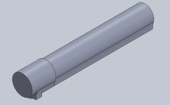
Didn't get an absolutely absurd amount done due to the above mentioned search for that dimension, but I ended up simply measuring and going with what seemed most reasonable. Might do more work on it, if so then I'll edit this message with that. Until then, here is what is done: 1690073518630.png
As you can see, I got the entirety of the 'front ring' portion done, including the angle on the front of the recoil lug interface. The doc is pretty thorough and legible on the portion 'behind' what I have gotten done, it should go much faster than this. In order to make it easier on my computer I am going to avoid doing the chamfers until everything is done (AKA after the camming surfaces are calculated and added)
 
Didn't get an absolutely absurd amount done due to the above mentioned search for that dimension, but I ended up simply measuring and going with what seemed most reasonable. Might do more work on it, if so then I'll edit this message with that. Until then, here is what is done: View attachment 355374
As you can see, I got the entirety of the 'front ring' portion done, including the angle on the front of the recoil lug interface. The doc is pretty thorough and legible on the portion 'behind' what I have gotten done, it should go much faster than this. In order to make it easier on my computer I am going to avoid doing the chamfers until everything is done (AKA after the camming surfaces are calcul
In the file labeled as 'receiver_lr' in the bottom right of the image is the text 'zeichnung besteht aus 2 blatt' which means 'this is page one of two' if I remember correctly. Do you have the second page? I am currently making decent work of what you've provided so far. When I stop working on it for the day I'll post a screenshot of the progress, currently slamming my head against the wall trying to figure out the smaller diameter for the circular portion of the receiver that is 'behind' the large ring portion from which the other cuts are made. I might just go to my rifles and measure it with calipers then try to reason out what it is, most of the measurements I made with them on the prior attempts were reasonably close to the actual dimensions.

Also, if I can be spoiled, could you possibly rescan that specific document with a higher contrast? I can't tell if my eyes are just bad or not, but I am having a decently hard time seeing the indicator lines. I currently am tracing over them with a pencil, so I think I can make it work as is, but it'd be a convenience if the contrast was upped. Once again, thank you either way.
Hi
What radius are you interested in? Mark it on the drawing.
 
Here is another update, found the time to get far more done than last time:
1690677229967.png
Next will be the internal camming surfaces, the trigger and firing pin components, the chamber area, and then finally the fillets/finish removing the wall(that you can see).

If all goes well I'll see if I can get a prototype made on a plastic 3d printer, and check that against multiple mauser 98 bolts for function. While that is happening I'll work on the bolt components.
 
Here is another update, found the time to get far more done than last time:
View attachment 356366
Next will be the internal camming surfaces, the trigger and firing pin components, the chamber area, and then finally the fillets/finish removing the wall(that you can see).

If all goes well I'll see if I can get a prototype made on a plastic 3d printer, and check that against multiple mauser 98 bolts for function. While that is happening I'll work on the bolt components.

Hey,
I noticed an inaccuracy. It is better to fix it now, at this stage, as it will be hard to change the part later. That's my opinion.
Best regards.
 

Attachments

  • 1690677229967.png
    1690677229967.png
    314.8 KB · Views: 216
  • P1170823 lr 2.jpg
    P1170823 lr 2.jpg
    598.7 KB · Views: 256
Last edited:
Hey,
I noticed an inaccuracy. It is better to fix it now, at this stage, as it will be hard to change the part later. That's my opinion.
Best regards.
Thank you, for some reason I flubbed and didn't realize the surface wasn't straight up and down. I'll revisit it and look closer to figure it out.
 
Hi!

I'm looking for those sizes too, and I'm not having any luck finding them yet.


Thanks.
 

Military Rifle Journal
Back
Top